Latest update 1 January 2007TYPE APH-5 PILOT’S PROTECTIVE HELMET Description
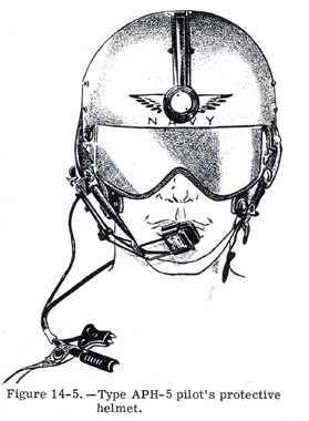
The APH-5 protective helmet, shown in figure 14-5, is the Navy’s newest. The helmet is available in large and medium sizes. The complete unit consists of an outer shell, energy-attenuating liner, sizing pads, integrated visor, earcup assemblies, communication cord, oxygen mask mounting tabs, nape strap, and adjustable chinstrap. Furnished with the unit is an envelope with four shims an two screws for horizontal adjustment of the earcup assemblies. A sizing instrument, to be utilized in fitting the helmet properly, is issued with each helmet.
OUTER SHELL
The outer shell provides force-distribution and penetration-resisting properties. The oute
shell is molded from glass fabric and a polyester resin.
ENERGY-ATTENUATING LINER
The liners are provided to absorb or dissipate impact energy and thus prevent skull
fracture or brain injury, or both. The three sections of the liner, which are made of
cellular polystyrene sheets, are molded to fit closely the inside contours of the outer
shell.
SIZING PADS
The sizing pads permit fitting of the helmet to an individual’s head contour with eth
proper balance between stability and comfort. The sizing pads are supplied in the basic
configurations – back, crown, and front, also in two basic thicknesses – thin
and thick. The pads are leather covered, miniature size to improve comfort by reducing the
discomfort that could possibly result from internal heat in the helmet. Aviation
Clothing and Survival Equipment Bulleting No.3-57A, authorizing modification of the
sizing pads, must be complied with on all helmets that are in service and not already
modified.
VISOR
The integrated visor provides protection from sunglare, windblast, dust, foreign
particles, and flash fires. It has excellent optical properties and crack propagation
resistance and is protected from damage when in the UP position by a housing. The housing
is molded from a glass fabric and a polyester resin, similar to the outer shell.
Two colors of visors are available for use in the helmet assembly; clear and neutral grey.
The neutral grey visor, which is darker at the top than at the bottom to afford maximum
protection from sunglare and to facilitate reading of the instrument panel, is currently
supplied in various densities. This range of densities satisfies various requirements for
special visual conditions and/or individual preferences dictated by such factors as the
demand by blond or light pigmented individuals for darker lenses. The relative darkness or
degree of visible light transmittance is indicated by white markings on the inside edge of
the visor. This marking can be seen more readily by removing the visor from the housing.
Table 14-1 shows the markings and the percentage of light transmittance.
| Table 14-1 – Visor marking and percentage of light transmittance. |
|
|
| Marking | Percentage of light transmittance | |
D |
10 to 20 percent inclusive | |
XD1 |
8 to 10 percent (medium dark) | |
XXD |
6 to 8 percent (dark) | |
XXX |
5 to 6 percent (very dark) | |
*D |
10 to 20 percent inclusive | |
*XD |
Under 10 percent | |
| * In the initial quantity of helmets issued to the fleet, these two types of neutral grey visors were installed. | ||
Due to the manufacturing processes, it is impractical to control transmission of the various filter visors produced. In view of this practice, medium and large size visors with varying percentages of light transmittance are carried in the supply system under a single stock number. It is recommended that personnel check lenses at squadron level to obtain individual preferences before obtaining from supply.
EARCUP ASSEMBLIES
The earcup assemblies contain the earphones and improve radio reception by providing good
attenuation of outside noise. Each assembly consists of a phone housing of cellular
polystyrene and an ear cushion assembly composed of a soft neoprene rubber foam body and a
di-isocyanate foam facing cushion. If the earcup assemblies are loose and need adjustment,
the four shims and two screws contained in the envelope should be utilized to accomplish
the lateral adjustment. Proper fit of the earcup is necessary for proper radio reception.
The earcups have been designed with a large ear cavity to minimize the possibility of
pressure discomfort to the ear. A vinyl film washer is inserted between the earcup and the
shell to prevent movement of the earcup assembly in the event that the shims are not
necessary for lateral adjustment.
COMMUNICATION ASSEMBLIES
The communication cord is designed to provide electrical connections between the earphones
and the aircraft radio facilities. The molded junction block connecting the four earphone
leads to the cord is located in the back left center of the helmet. It is seated in a
cutout in the middle section of the cellular polystyrene energy-absorbing material.
The installation of the boom type microphone should be accomplishes as follows:
Pre-position the boom mike assembly on the side of the helmet. Swing the boom through a
full arc to determine the optimum point. Then, scribe the intended position of the
bracket, drill holes accordingly, and attach. The position will vary with the face shape
and personal preference. Boom type microphones are not provided with the helmet assembly
and must be ordered individually.
Type H-87A/U earphones are installed in the cellular polystyrene earcups of the ear
cushion assembly. Each earphone is connected to the two wires leading out of each side of
the molded junction block of the communication cord.
In order to properly fit the APH-5 helmet, the various attachments must be utilized. The oxygen mask mounting tabs provide a means of securing the oxygen mask to the face and assist in achieving a seal around the face in the oral-nasal area. The tabs are mounted in such a manner as to permit an even distribution of pressure over the sealing area of the oxygen mask. Another function of the tabs is to assist in retaining the helmet and mask during bailout at high speeds. The chinstrap is also designed to retain the helmet during emergency escapes at speeds in excess of 500 knots.
The nape strap is designed to increase helmet retention. It is important to keep in mind that the full effectiveness of the nape strap cannot be realized unless the chinstrap is cinched up in a snug position. Retention of the helmet under emergency conditions can be insured only by the proper fitting of the helmet to the user’s head and the proper utilization of the chinstrap. The nape strap merely increases the retention provided basically by the chinstrap. It must be remembered that the cinching up of the chin strap is an additional adjustment that must be done after the oxygen mask is positioned on the face.
To properly use the sizing instrument and fit the APH-5 helmet for optimum comfort and stability, the following instructions should be applied:
Determine the head length. The helmet size and liner thickness are indicated on the horizontal bar. Determine the head breadth. When the head length dimensions provide a choice between two sizes of helmets, the head breadth should eb the factor in determining the proper size. If the head breadth is over 6 inches, use the large size helmet with all thick liners (sizing pads). If the head breadth is under 6 inches, use the medium size helmet with all thin liners.
After the liners have been inserted, have the pilot don the helmet. The proper way to don the helmet is to place the thumbs over the ear cushions, and pull outward on the helmet; insert the forehead in the area between the thumbs, and complete donning by rolling the helmet backwards until it is positioned to his satisfaction.
COMFORT
If the helmet is not comfortable to the pilot, make the following suggested revisions: If
a thick liner is used in the area affected, substitute a liner of lesser thickness. If teh
pressure point remains, choose the next larger size and use the thick liners in an
unaffected area and thin liners in the affected area.
STABILITY
To obtain maximum stability, a snug fit is required. It is possible that stability has
been sacrificed for comfort in relieving the pressure points. Proper stability can be
determined by vigorously shaking the head. Keep in mind that the pilot must be the judge
in determining the correct balance between comfort and stability of the helmet.
After the fitting has been accomplished and sufficient flights have been made to determine
adequacy of fit, the unused sizing pads, shims, and sizing instruments should be returned
to local supply for reissue. In addition, clear visors that are not being used should be
returned to supply for reissue.
There will be a minimum amount of maintenance on the helmet since the pilot keeps it in his possession. On occasions, there will be some maintenance such as re-cementing loose sizing pads, liners etc. When not in use, the helmet should always be kept in the bag provided.
CHANGING THE VISOR
Changing the visor on the APH-5 helmet is a simple task, but the following procedure
should be followed: Locate the visor in the UP position. Disengage the keepers by lifting
up on their thumb tabs and pivoting them downwards 90 degrees.
Press down the center portion of the button and lift up the peripheral plastic section.
When the button spring is fully compressed, turn the entire button 90 degrees and remove
the visor from the bottom of the housing.
To insert a visor replacement, this procedure is reversed.
CLEANING THE VISORS
The following procedure for cleaning visors is recommended:
Wash the visor with mild soap and water, using clean rags. If the visor is still soiled or
if it is necessary to remove minor scratches, use polish. Specification MIL-C-18767 polish
is used on acrylic plastic. To preserve the surface, use polishing wax for the final
application. The wax to be used on the visors can be ordered by stock number FSN
R37930-266-7125-G600.
REPLACEMENT OF ELECTRONIC EQUIPMENT
To replace communication cord, remove the ear cushion assembly from the helmet by removing
the screw on each side of the outer shell. The earphones can be disconnected from the
wiring harness after the ear cushion proper has been removed from the polystyrene housing.
At this point, release the screw engaging the clip and junction plate at the rear portion
of the helmet for complete removal of the communication cord.
To replace the communication equipment, reverse the procedure.